After three successful years with our previous robot Auri, the team decided to retire it and take what was learned to design Arctos. Auri served us remarkably well placing 4th in the 2019 Robosub competition. However, as the competition consistently offers unsolved challenges, ARVP always strives to do better and improve on our existing systems. With Arctos, ARVP prioritized functionality and modularity in a minimalist design. While previous robots were burdened with drag-inducing panels, Arctos features a lightweight yet sturdy frame. The hull was also completely overhauled, shifting from a cylindrical design to a rectangular one for improved space efficiency.
Almost all sub-assemblies were redesigned for the 2020 competition to improve in areas of risk management, diversification, and efficiency. Arctos features more components than ever before, including a claw, a bottom camera, spring-loaded torpedoes, a stereo front camera, 8 thrusters, a marker dropper system, a Nortek DVL 1000, and a Teledyne hydrophone array. As a nod to our previous robot, Auri, the overall design retains a Star Wars-inspired look, with aluminum wings framing the whole body.
The most notable addition is the mechanical arm and claw system for manipulation tasks. Accompanying this is a bottom camera enclosure to allow for downwards facing vision. Another notable change is that the team moved away from a 6 thruster configuration to an 8 thruster configuration, with 4 facing vertically to improve the control system's overall reliability and stability along the pitch and roll axes. Lastly, as with all great Autonomous Underwater Vehicles (AUV), the center of mass (COM) and center of buoyancy are aligned and are close together to increase stability while maintaining maneuverability. All thrusters were positioned to be on planes in line with the COM to further improve control. The goal of the mechanical team this year was to stick to basics to generate innovative ideas that highlighted AUV fundamentals.
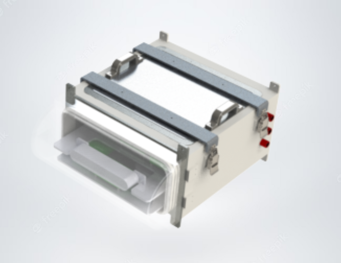
At the core of our robot is the hull assembly, which is the brains of the operation. The hull assembly was completely redesigned to be different from Auri where the team moved from a cylindrical enclosure to a rectangular one. A cylindrical hull is advantageous with regards to pressure distribution and drag but it did not optimize space usage. Contrastingly, a rectangular hull enables high spatial efficiency and easy manufacturing with the ability of stacking electronic components for easy assembly. This assembly is capable of enclosing all electronics including our 5 LiPo batteries, IMU, and processor (NVIDIA Xavier) and still has room for electronics expansion. Using a centrally located rectangular hull also decreases the amount of cables required to connect components, which increases cable management and organization. Moreover, all external connections such as penetrators, bulkhead fittings, and SubConns are placed at the back panel which are easily accessible. A cylindrical hull made it difficult to reach all connectors and there was limited real estate to place them. The hull itself is fabricated from 6061 aluminium with two acrylic access points that are sealed using Parker standard O-rings in a double gland seal configuration and compression latches. Almost all of the hull is bonded rather than welded which reduces metallic discoloration while making assembly easy and reversible, if need be.
The frame assembly of Arctos was designed to be more functional than Auri’s. We removed sheet metal parts that could increase drag while maintaining a fundamentally sound design. This entails that simple parts were used such as aluminium angles and sheet metal, which lowered manufacturing costs and time. Like Auri, the frame assembly has a unified fastener system which decreases confusion during assembly and minimizes the parts needed. The most significant feature about the frame assembly is the welded vertical wings that use 1” OD structural tubing to provide an incredibly sturdy base while remaining very rigid. Another advantage of using tubing is that it has high strength relative to its weight. The frame assembly is the skeleton of the robot while housing all subassemblies while providing protection. Because of this, the frame has the ability to be expanded in length and width by simply changing the length of aluminium angles used. Overall, the assembly is lightweight, simple, sturdy, and adaptable and the team is excited to see where it takes us in the next few years.
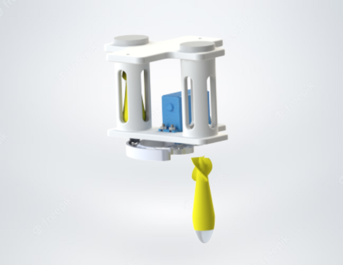
The marker dropper system is located on the underside of the frame. The system consists of an IP67 rated servo, 2 marker droppers, and a 3D printed housing. The droppers are oriented vertically and have markers with a hydrodynamic profile. They can be loaded into the mechanism by removing the top caps and are held in place by a 3D printed gate that is locked with the servo’s rotor. Controlling the system is easy since the motor’s range of motion permits independent marker release which will increase the accuracy of the droppers.
The torpedoes assembly is located at the bottom center of the frame and was highly refurbished for this year’s competition. This year’s redesign of the torpedo launching system was focused on finding a more cost-effective and safer method of launching projectiles. Unlike Auri, which uses a compressed gas actuated system, a compressed spring system was used. Because of this, common issues such as gas leaks or expensive replacement parts have been eliminated. The assembly consists of 2 stainless steel compression springs, a 3D printed housing and auxiliaries, and an IP67 rated servo. The IP67 servo, coupled with a sheet metal gate system, allows independent release of each missile, which will improve the robot’s accuracy in torpedoes tasks. Also, a spring system entails easy replacement of missiles after each shot without the need of replacing a compressed gas canister, which is sometimes risky. Lastly, since bulky parts are no longer needed for a compressed gas system, the torpedoes assembly is approximately ⅓ of the weight compared to last year. We believe our new torpedoes will be a force to be reckoned with.
The sonar system this year will use 4 pingers compared to 3 last year. Therefore, a refurbished 3D printed mounting base was created for the new and improved hydrophone assembly. More details on how the hydrophone array works and is used are described within the electrical and software design sections further down.
The most exciting addition to ARVP’s arsenal of sub-assemblies is the mechanical claw and gripper system. As more tasks are becoming manipulation based, the team thought we would gain an edge by creating a gripper system. The system has an aluminium structure to increase rigidity and strength while being lightweight. With 4 servos, 2 sets of linkages, and a maneuverable gripper base, the claw maintains 3 degrees of freedom. The manipulator itself will be 3D printed using various materials that give it traction to hold items without the fear of slippage.
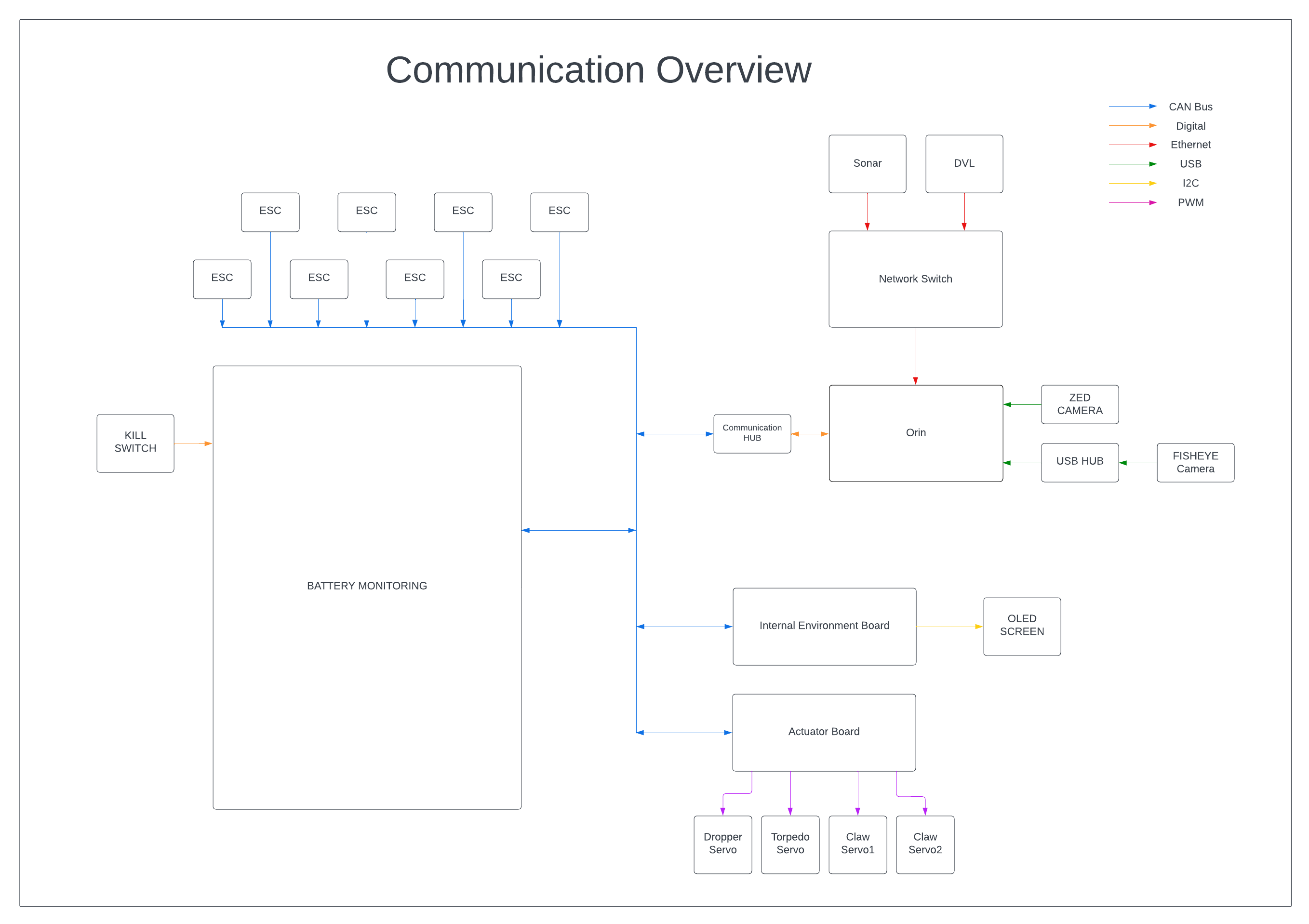
Arctos shares much of Auri’s infrastructure. In order to bring up new systems quickly, it was essential that we re-used as much of the robot as possible. However, Arctos offers a few key advantages over the old design that allow it to operate better. These incremental improvements over previous years are discussed in more detail for each electrical system below.
With the new hull shape, we are able to fit components in a more space-efficient and serviceable way than previously. This frees up more room for more experimental subsystems and the increased amount of power delivery we need.
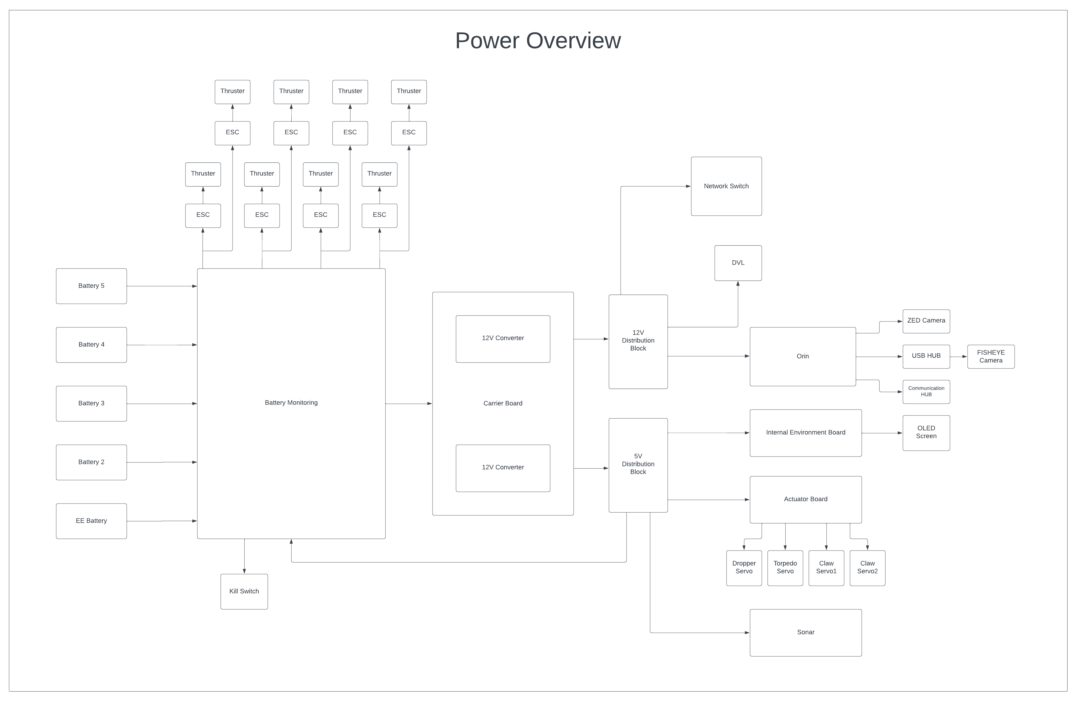
In order to accommodate the increased number of motors, an extra battery was required, and the battery monitoring subsystem had to be re-designed to allow for this.
The multi-function actuator board was upgraded in order to accommodate the different voltages and extra channels required for the servos on the new arm assembly. It keeps the LED indication functionality which lets us see Arctos’ current state even without a connection.
To provide regulated power for all internal subsystems, Arctos uses the same modular buck-boost switching converters and carrier board from Auri. The flexibility built into this system has allowed us to simply add an extra channel to support the required servo voltage.
The communications hub, providing CAN bus connectivity and breaking out several I2C and UART interfaces, was miniaturized and modified for use on the Jetson Xavier being used inside of Arctos. This board allows the Jetson to communicate with the rest of our subsystems and directly attach to a few key sensors.
An experimental feature this year is a battery levelling system, which is able to draw power from the motor batteries once the main compute battery is drained. The capacity inside of the compute battery has been the bottleneck for run time in the past, and this allows Arctos to extend that capability, while also improving wear levelling on all of our batteries.
Our sonar preprocessing board has been upgraded from 3 to 4 channels of hydrophone inputs. This can give us more accurate pinger position information.
As well, an integrated data acquisition system has been developed that connects directly to the preprocessor board, which allows us to remove the temporary Beaglebone + PruDAQ setup that was used previously, reducing complexity, power consumption, and total board space.
In the perception faze of the pipeline, the robot takes in information about its surroundings to answer the question “Where am I?” There are a number of areas the robot takes information from.
A ZED stereo camera is installed on the robot. With it the robot can record camera footage and analyze the images. We use a deep-learning based approach to analyzing images for props. Specifically, we use YOLO v3 for rapid object detection. We also use YOLACT for more detailed image segmentation.
In the left image you can see YOLO v3 drawing bounding boxes around areas of importance for a torpedo target. On the right you can see a gif of YOLACT actually highlighting the entire detected object.
By using a stereo camera the robot can extract additional information from its environment. A stereo camera is a device with two cameras that are offset from each other by a known distance. The two cameras record independently from each other. By comparing the images produced, distances can be triangulated from an object to the camera. Below is an image of what this looks like in the simulator. The darker a pixel, is the closer it is to the camera.
The simplest sensor on the robot is the depth sensor. It measures water pressure and from that calculates the robot’s depth underwater. Despite being so simple, it is the only sensor that can directly measure position along the z-axis.
The next sensor is an Inertial Measurement Unit (IMU). IMUs are highly sophisticated pieces of technology. ARVP uses a LORD MicroStrain 3DM-GX5-25 AHRS. This model contains an accelerometer, gyroscope, and magnetometer. With it the robot can directly measure: Acceleration, Magnetic Field, Angular Rate, Pressure, Up Vector, North Vector, and Ambient Pressure. This IMU not only makes measurements but it also calculates Attitude and a Gravity Vector. The most important measurements the robot records are Acceleration, Angular Rate, and Attitude. With these measurements the robot can tell what direction it is facing and what direction it is accelerating.
The last and most expensive sensor the robot uses is a Doppler Velocity Log (DVL). ARVP uses a Nortek DVL1000. A DVL is a specially designed acoustic sensor for subsea applications that cannot use a GPS. It uses the Doppler Effect by producing 3 acoustic signals and then measuring their return frequencies to calculate the velocity of the sensor. When ARVP obtained a DVL, it completely changed the software architecture. It allowed the team to estimate position with some degree of accuracy
At competition, one of the tasks includes an acoustic pinger. The robot is supposed to navigate on top of this pinger and then surface. This is by far the most difficult task to complete. Detecting and calculating the direction of a ping has taken years of development to get to a reasonable level. To detect a ping we use three hydrophones that are held in an ‘L’ formation by a custom frame. Each hydrophone measures a ping at a slightly different time. By measuring the time difference between hydrophone signals, the direction of the pinger can be calculated. This is, at best, very noisy so pinger estimates need to be thoroughly evaluated. For this, the robot uses a Particle Filter. A test run can be seen in the adjacent gif.
One of the benefits of using a DVL and having good localization is the ability to create a map of the robot and its surroundings. By creating a map, the robot can articulate its own position and estimate its position with respect to the props in the pool. The mapper takes in information from robot position estimates and prop position estimates and filters it to reduce error. In the adjacent image an example of the mapper can be seen. On the left is the robot, and to the right are a gate, a buoy, and a torpedo target. Around each prop is an ellipsoid which visualizes the confidence the mapper has in that props position. In other words, the mapper believes there is a 95% chance that the prop is in that ellipsoid. Over time, the ellipsoids shrink as the mapper’s confidence increases.
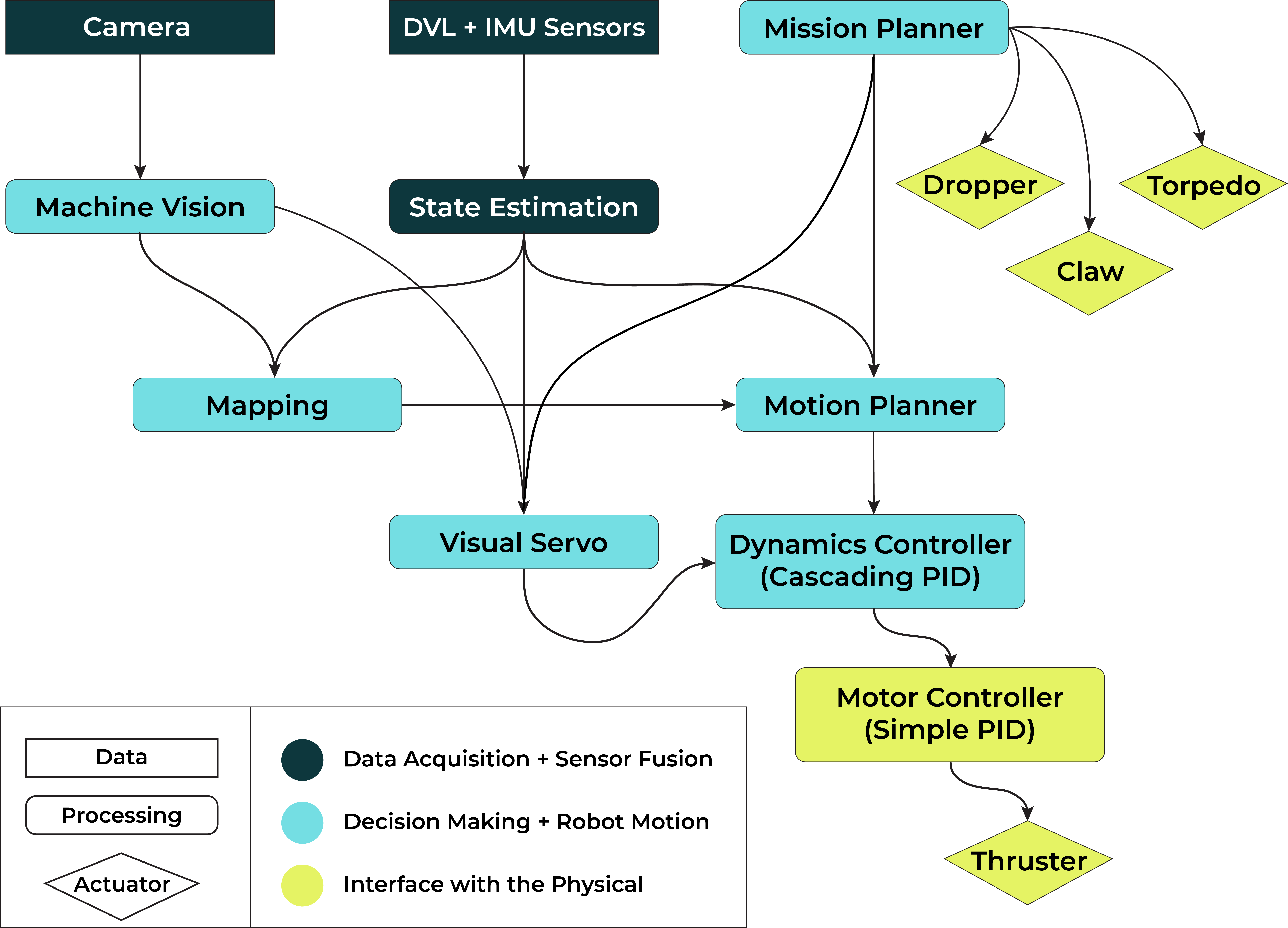
Once the robot has taken in sensor information and a position estimate is formed. The robot must then answer the question “What should I do?” This is where the mission planner comes in.
The mission planner monitors the state of the robot and of the props and sets goals to drive the robot. It does not directly control thrusters but rather it sets targets for the control system to reach. For example, the mission planner may see that the robot is at position x=1, y=1, and z=5 (this notation is cumbersome so instead we will refer to positions in this form, (x,y,z) where z increases as the robot goes deeper underwater.) but the prop for the next task is at (5,3,5). The mission planner might then set a goal somewhere near the prop like (4,3,5). Once a goal is set, the mission planner is done. It does not determine the path the robot will take to a goal; that is handled by the robot’s control systems.
Setting goals is not the only function of the mission planner, it also handles time management. At competition, the robot has half an hour to complete as many tasks as possible. That may sound like a fair amount of time but in actuality it is very limited. Moving from task to task can take ~4 minutes and tasks themselves can take an additional ~2 minutes. If the robot intends to do 5 tasks, then the mission should take ~26 minutes in total. So with this in mind, the robot cannot be allowed to stall at a single task for too long. To account for the time limitation, each goal set by the mission planner has a predetermined timeout. If the timeout is reached and a goal has not been met then the mission planner will move on to the next goal.
One of the biggest challenges with autonomous robotics is that once you start the robot on a mission you completely lose control. As per the rules of competition, we are not allowed, in any way, to communicate with the robot once it starts. That is why it is important to have a robust mission planner. If there is some sort of failure, the mission planner is there to cut losses and continue on with the mission.
The controllers on the robot are the processes that convert positional targets provided by the mission planner into thrust efforts over time. They answer the question, “How do I reach my goal?”
To illustrate what controls do let us consider an everyday example. Imagine you are driving a car on a highway and you wish to maintain your speed with traffic around you. If your car moves too quickly you could hit the car in front of you. If your car moves too slowly, you could be hit by a car behind you. So, let us say you try and keep two car-lengths between you and the car ahead of you. But, how can you do this?
The only way you can control your position relative to the other car, let us refer to this as relative position, is by manipulating your car’s accelerator. The accelerator does not directly control your relative position but you, as an intelligent human being, understand that by accelerating or decelerating you can change the speed of your car. By changing your speed you know you can increase or decrease your relative position. So, in this way, you have an intuitive understanding of the car and how the accelerator affects your relative distance.
Let us say you are 3 car-lengths away from the car ahead of you. Since you want to maintain a distance of 2 car-lengths you should accelerate. But, once you reach two car lengths you realize you are going to overshoot your goal by 0.5 car-lengths. So you decelerate but then undershoot but by 0.25 car-lengths. By continuing to accelerate and decelerate you eventually reach your goal of 2 car-lengths.
This example may be extremely simple but let us analyze it in terms of a control system: you are the controller; the target was a relative distance of 2 car-lengths; the state was your acceleration, speed, and relative distance; the system was the two cars moving at varying speeds; the dynamics of the system followed simple Newtonian Physics; and the control input was the accelerator. You, as the controller, were able to convert a target into a series of control inputs over time.
Controlling an underwater robot is far more difficult than controlling a car. On Arctos, there are 8 thrusters: 4 pointed along the z axes, 2 pointed along the x-axis, and 2 along the y-axis. They must be controlled in such a way that the robot never becomes unstable. An example of a fragile control system would be one which was assumed to never rolled or pitched so that the thrusters along the z-axis always pointed up and down. Now if this robot were to tilt even slightly, that would result in a complete failure. As can be seen in the diagram, a small deviation cannot be corrected so the position of the robot degenerates into failure.
So the robot’s control system must be able to recalculate thrust efforts dynamically such that there is always a net downward force to counteract buoyancy for any possible orientation. In other words, the control system must be able to control all axes of movement simultaneously.
The next challenge for the control system is the weight distribution of the robot. At competition components are moved around constantly. This has a pronounced effect on how well the robot is able to control itself. For this reason, it is important that the control system is flexible enough to handle changes to the robot very quickly.
At ARVP, we use a Linear Quadratic Regulator (LQR) control system.
In mathematical terms this process is described with this equation:The main focus of an LQR control system is to achieve and hold a target configuration for a given linear system using an optimal control law. The optimal control law is a set of differential equations that minimizes a cost function which typically depends on the state and control variables. An LQR control system generates the control law using four matrices. These matrices are the A, B, Q, and R matrices which model the physical dynamics, control dynamics, state cost, and control cost, respectively.
Juan Rojas & Nathan Liebrecht
Put simply, the purpose of an LQR control system is to reach and maintain a target state using a dynamic model of the system (A), a model of the control dynamics (B), and two cost matrices (Q and R). In the equation, x is the robot’s current state and ẋ is the robot’s state in the next instant. The A matrix describes how the robot behaves in an underwater environment. It includes buoyancy, frictional forces, gravity, and the plethora of other physical constraints that affect the robot in an underwater system. This matrix represents how the control believes the robot’s position will change given its current state (x). The B matrix describes how the control system believes it’s control input (u) affects the robot’s state. u can be changed at any time by the controller but every other variable must be calculated or measured.
To relate this mathematical representation with the previous car example, we may draw the following comparisons:
The big question now becomes how do we determine u ? The A matrix can be determined through analysis and experiments, the B matrix can be determined by analysing the robot’s thruster configuration, and x comes from sensor data and filtering. In the car example, you determine u by intuition (a little more, a little less) but the robot cannot rely on human input in the pool.
This is where LQR comes in. Put very simply, LQR is a complicated mathematical equation that calculates a u with a minimal ‘cost’ for a particular time instant. To determine cost we define two new matrices Q and R.
The Q matrix describes the cost for error in the state of the system (error in state refers to the difference between the current state and the target state). In other words, it is a weighting factor that prioritizes certain components of the state. If there is a large error but a low cost, LQR will not produce very much control input to reduce the error. If there is a very high cost then LQR will exert much more effort to reduce the error.
The R matrix is very similar but it assigns cost to the control inputs. If there is a low cost then LQR will exert much effort with that control input. If there is a high cost, then LQR will emphasize using other control inputs to reduce error. For example, let us say the robot is very slow when it moves left and right. We can assign a high cost to moving left and right so that LQR does not rely on lateral thrust to reach a target.
With these two cost matrices, LQR attempts to find the best u that costs the least. In doing so, it finds the optimal control input for that situation.
We have had tremendous success with using an LQR control system. Some of the benefits include:
To demonstrate how powerful our LQR control system can be, see this gif of AURI completing a barrel roll (aileron roll). This may seem simple but the control system must maintain three targets. A forward velocity, a rotational velocity, and it must maintain its depth.
Apart from being mathematically intensive, LQR has one major flaw. It only calculates a control input for a given time. There is no control over the path the robot takes when reaching its target.
To solve this problem we use a ‘motion_planner’ which, given a target position, generates a path to that position and then feeds a series of velocity targets to the control system over time.
This process can be described in the following flow chart:
Our most essential development tool is our simulation system, Gazebo. Designing an underwater robot requires huge amounts of testing. At best, we can only test our robot in the pool once a week for 2-3 hours. This cripples development so ARVP has created a simulator with realistic underwater physics.
By having a simulator, every developer can run tests in the comfort of their own dev machine. They can test their vision changes, mapping changes, control changes, localization changes, they can also test missions they have created. Of course, a simulator will never replace an in-person physical test but it allows the team to scale development with the number of developers.
Here we can see a screenshot of Arctos in our simulator. The environment is a representation of what the competition pool looks like.
ARVP’s code is mostly written in C++, C, and Python. Developers generally work in an Ubuntu 18.04 environment. The team makes good use of the Robot Operating System (ROS) Framework. ROS allows us to modularize our code with nodes in a publisher subscriber model. Functionality is divided into processes called nodes. For example, the mission planner has its own node, every sensor has its own node, and additional functionality can be added as a node. Information is distributed in a publisher/subscriber model. A node may publish messages (data) to a topic and any node that is subscribed to that topic will receive those messages. This allows nodes to distribute information on an as-needed basis which reduces overhead.