Kenai
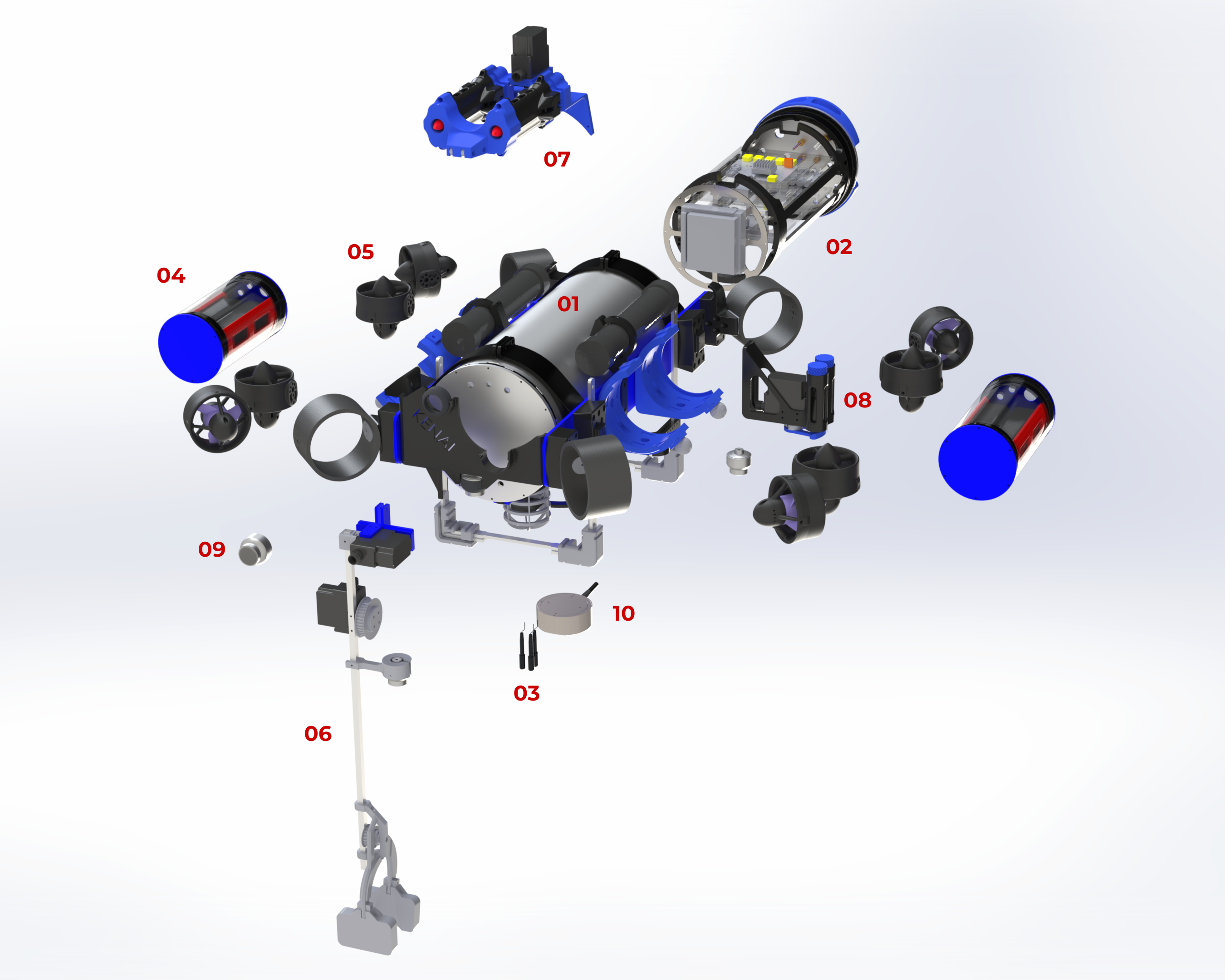
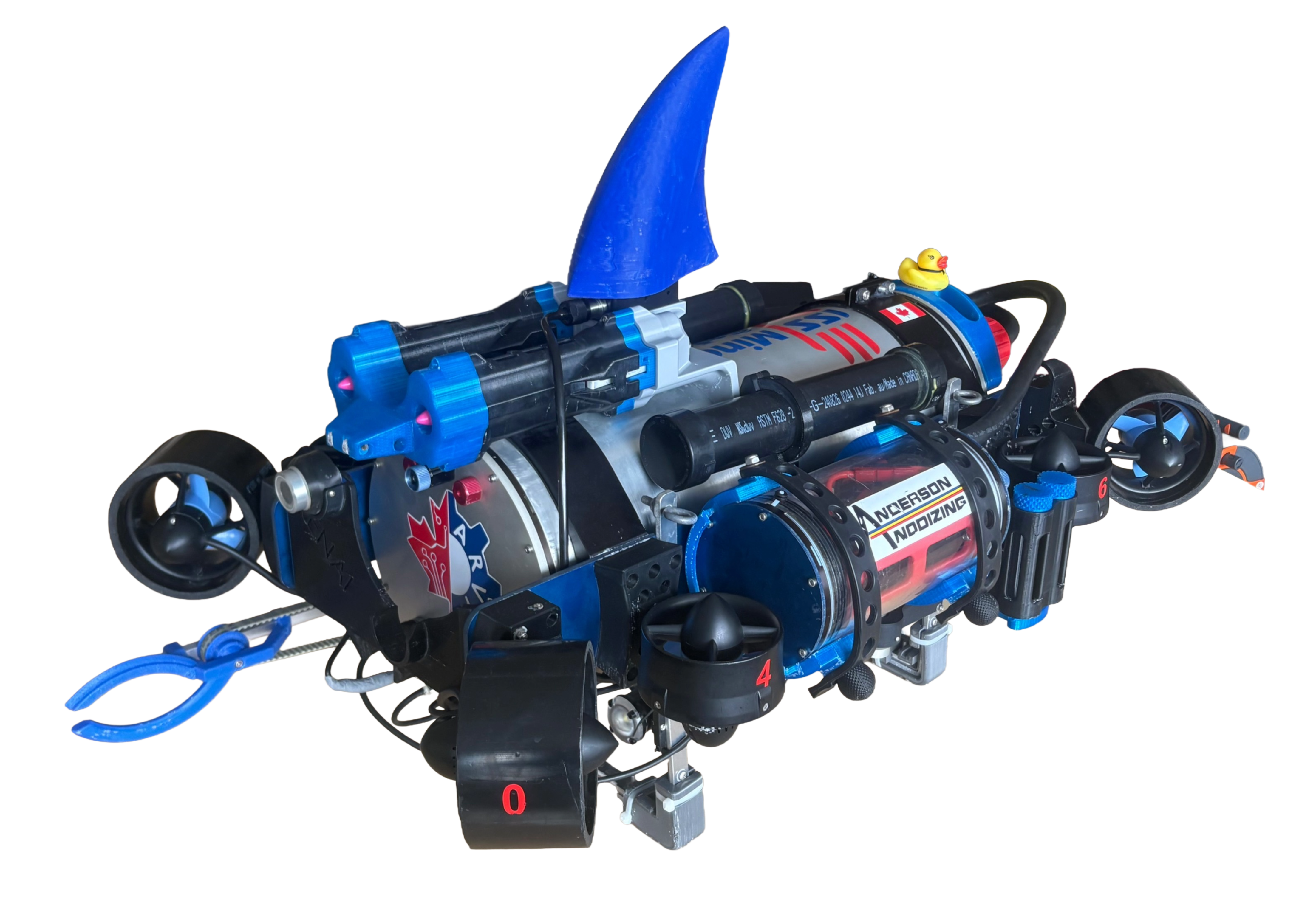
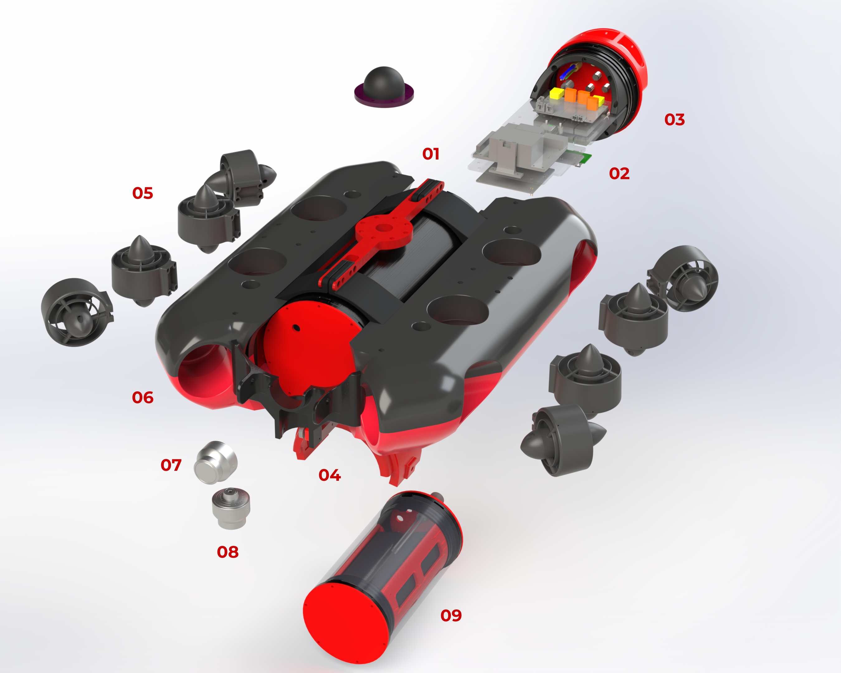
Kenai's mechanical design was grounded in reliability and simplicity. After a critical leak in Arctos' square hull, we shifted to a cylindrical aluminum design with double O-ring sealed end caps to eliminate unnecessary failure points. Subsystems were simplified and rigorously tested through accelerated lifecycle and standardized pressure testing.
While the frame is less modular, it's compact, cost-effective, and structurally robust. The robot's center of mass and buoyancy were aligned to improve stability, and external battery pods allow for quick swaps without opening the main hull. Every design decision focused on building a durable platform that can perform consistently under the rigorous testing conditions at RoboSub.
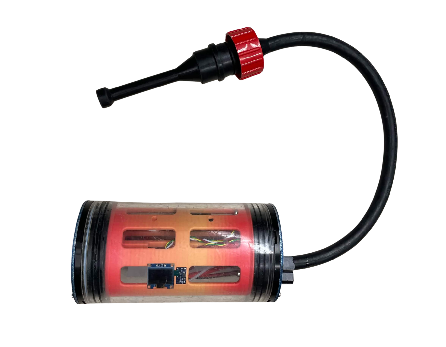
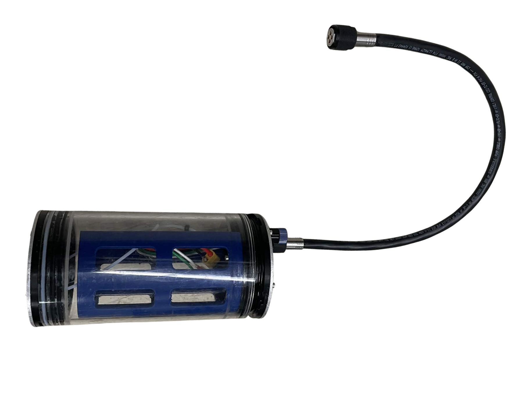
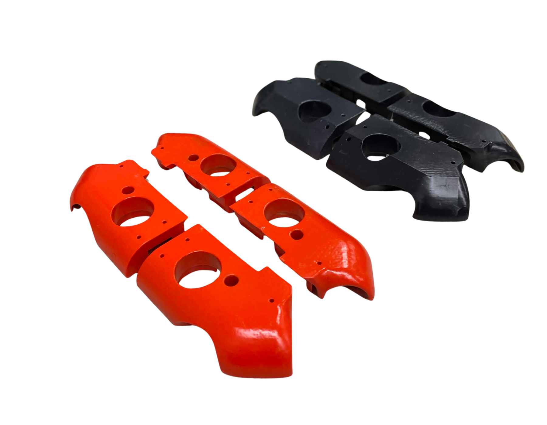
The external battery pods are small pressure vessels containing the batteries powering the main robot. These battery pods are mounted using easy snap-fit brackets, allowing for quick battery replacement without opening the main hull or exposing internal electronics.
Inside the pods are two printed circuit boards that detect the battery voltage and the internal pod pressure. The pod displays the data on a screen which is used to monitor the system and detect possible malfunctions. The system is activated externally using a magnet, eliminating the need to open the pod and allowing the internal system to remain sealed.
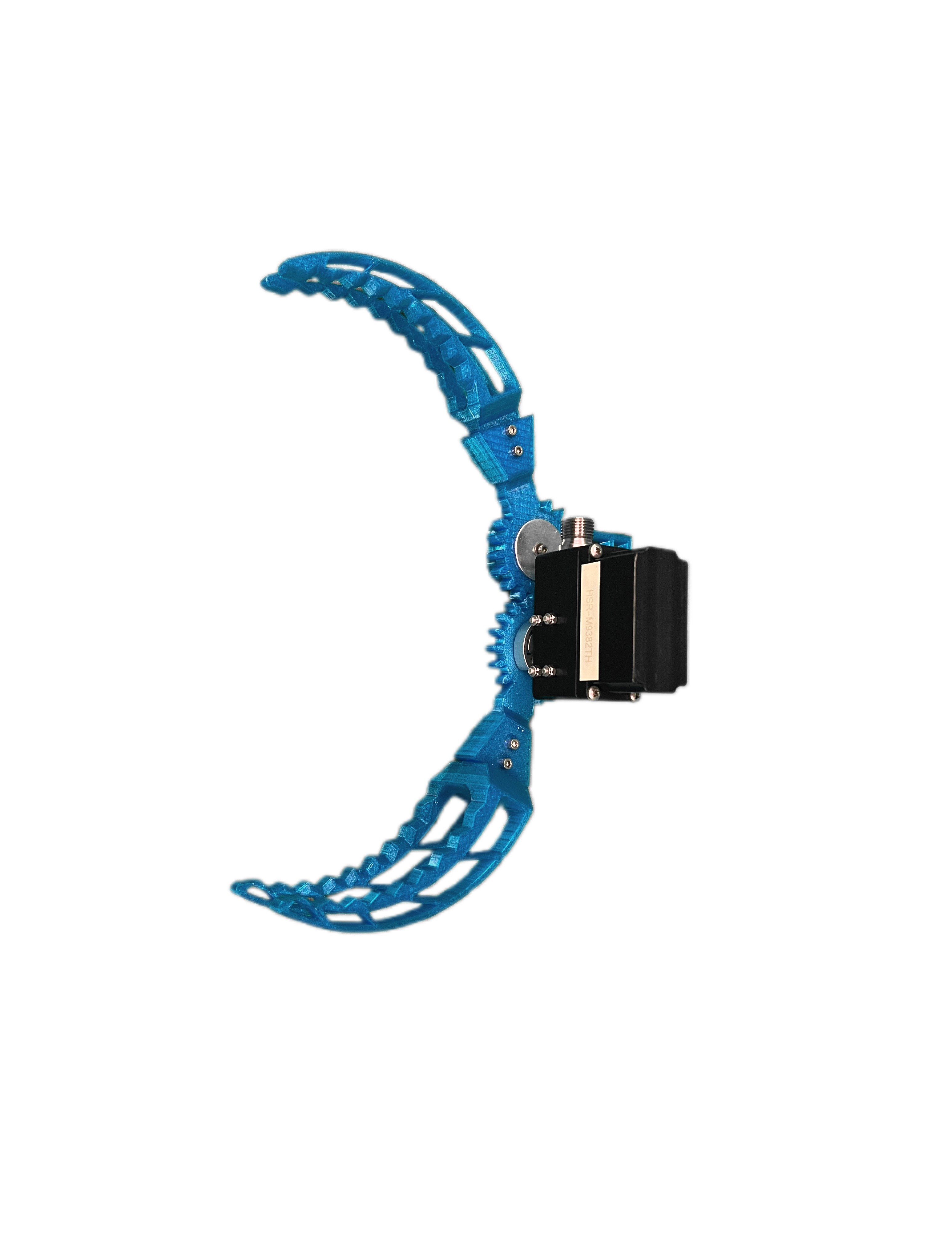
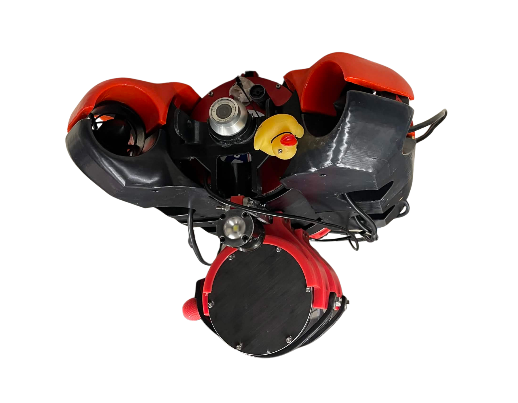
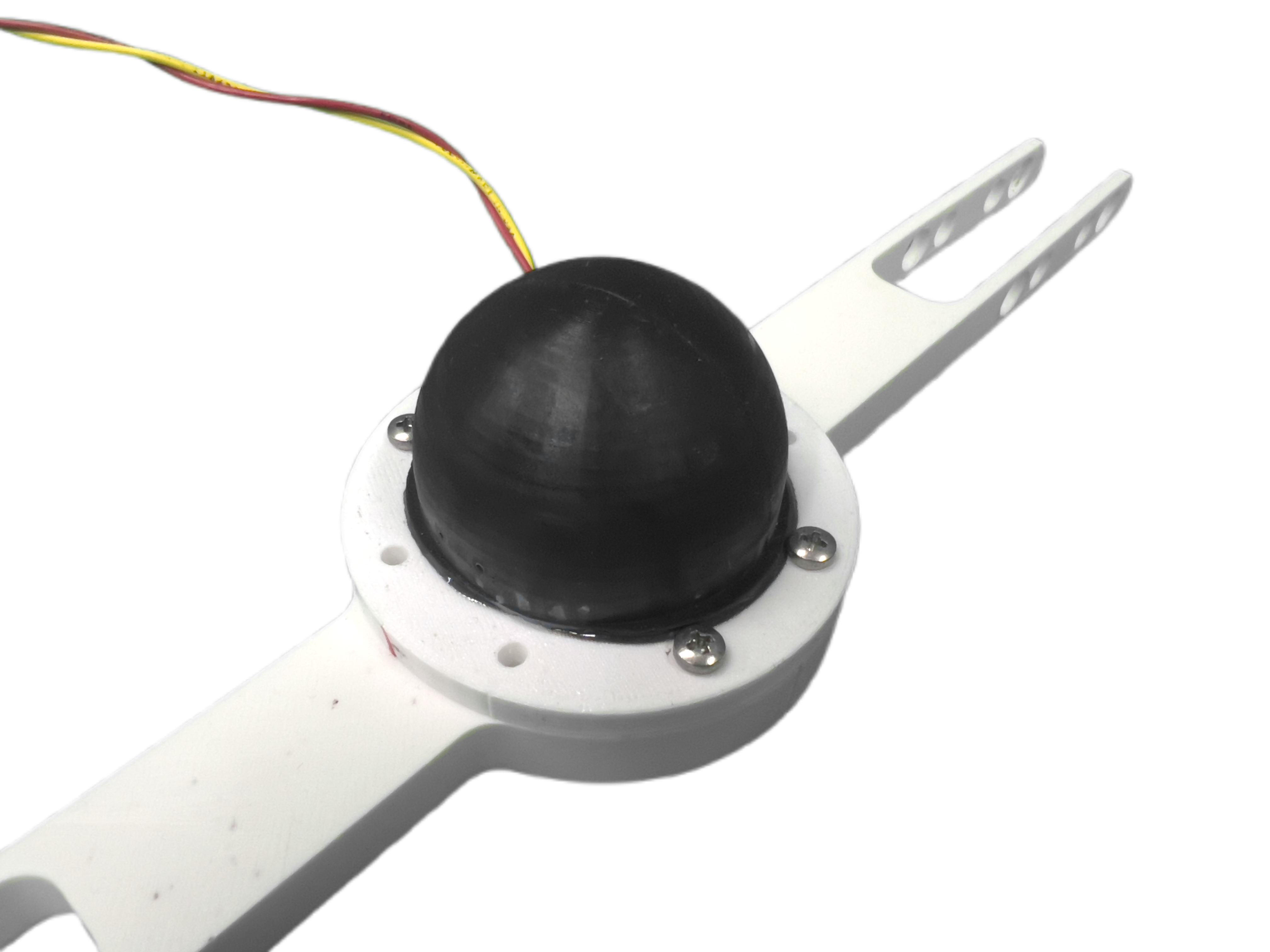
The claw has been entirely redesigned to operate with greater control, reach, and precision. The claw itself uses a servo motor and belt-drive to open and close its grippers, allowing for accurate movement and effective handling.
This year, an aluminum arm was added to the claw to provide improved mobility and an extended range of motion. The added reach allows the robot to stay farther away from the object, reducing the chance that the thrusters will disturb or move it. A camera is also mounted above the claw, providing a clear overhead view to assist with alignment and object retrieval.
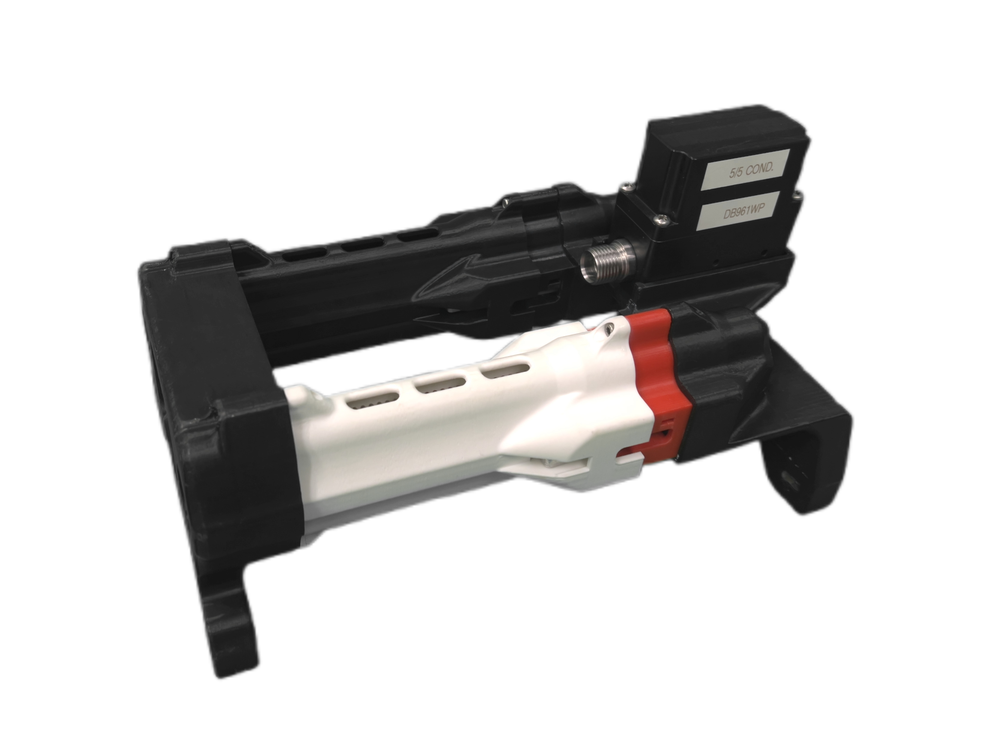
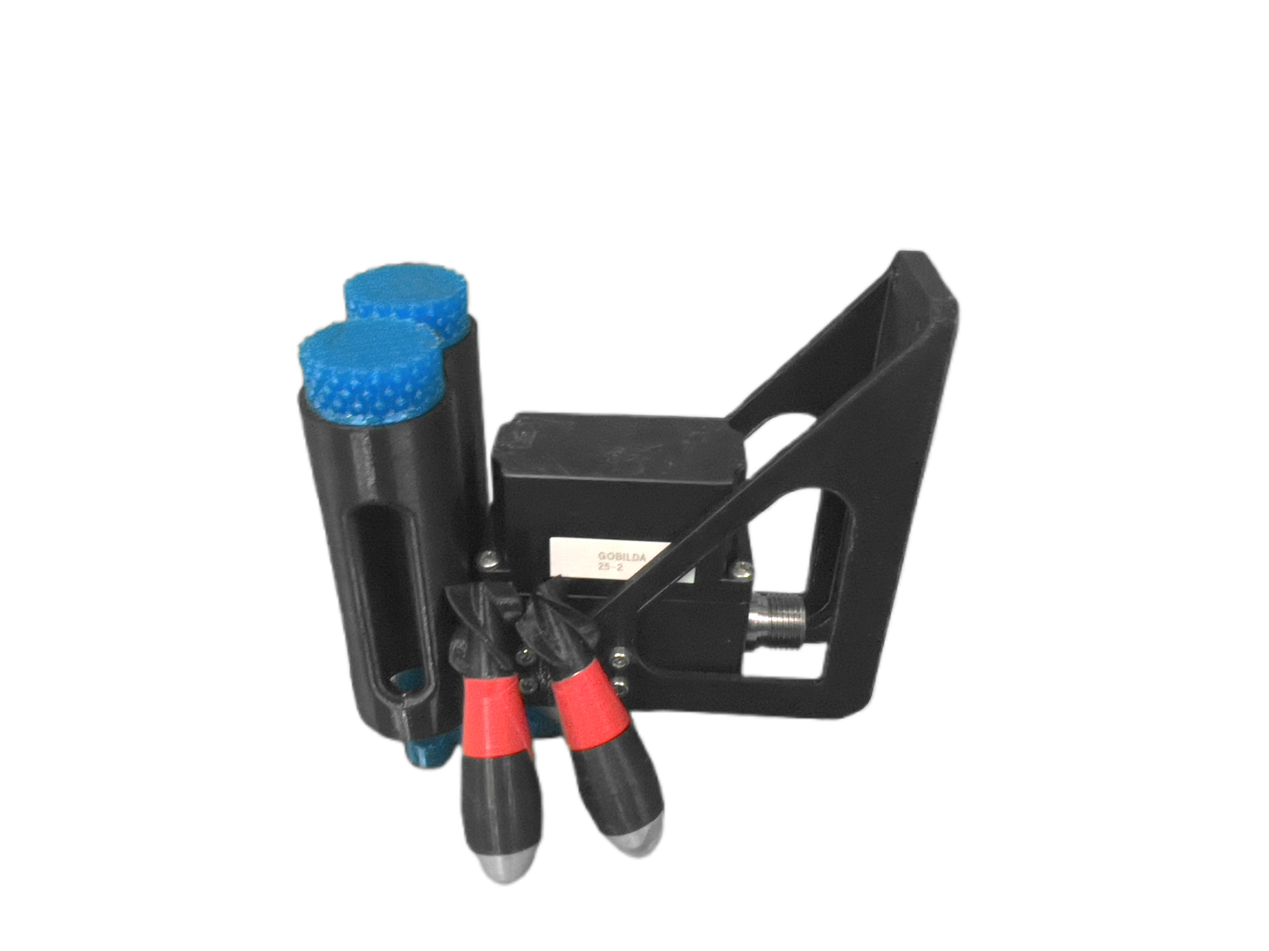
The torpedo mechanism was carried over from the RoboSub 2025 design with significant improvements to reliability and consistency when launching. They are spring-loaded with levers holding back the launch plate. To launch, the back of the levers are pulled together which allows the spring plate to release and fire our torpedoes.
While in the chamber, the torpedo is held in place by magnets embedded in the torpedo body and walls of the launcher to prevent unintentional escape. Rigorous accelerated life cycle testing was conducted underwater with springs of various spring constants to identify points of failure and reinforce internal structures to withstand the heavy use expected at RoboSub.
The dropper design is tried and true since RoboSub 2023. A housing contains the markers and a servo moves the blocker out from beneath the markers, letting gravity do its work.
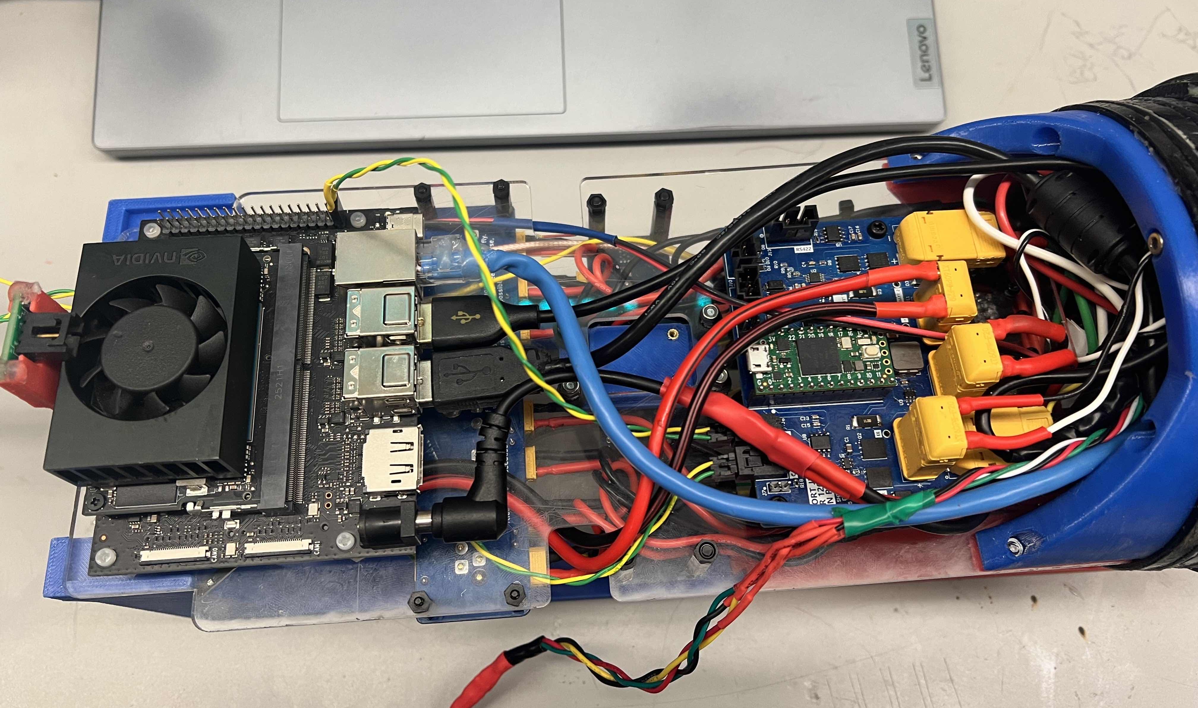
Our electrical system was redesigned from the ground up with a focus on reliability and serviceability. Many legacy boards were consolidated to simplify power distribution, while obsolete components were updated to ensure long-term support. Standardized connectors and wire gauges, improved board layout, and localized voltage regulation were all introduced to minimize points of failure and make the system easier to assemble, troubleshoot, and scale.
Custom acoustic systems were also designed and implemented to enable inter-sub communication and to handle the pinger task. Overall, this year's electrical philosophy prioritized building a cleaner, more robust foundation that's harder to break and easier to fix.
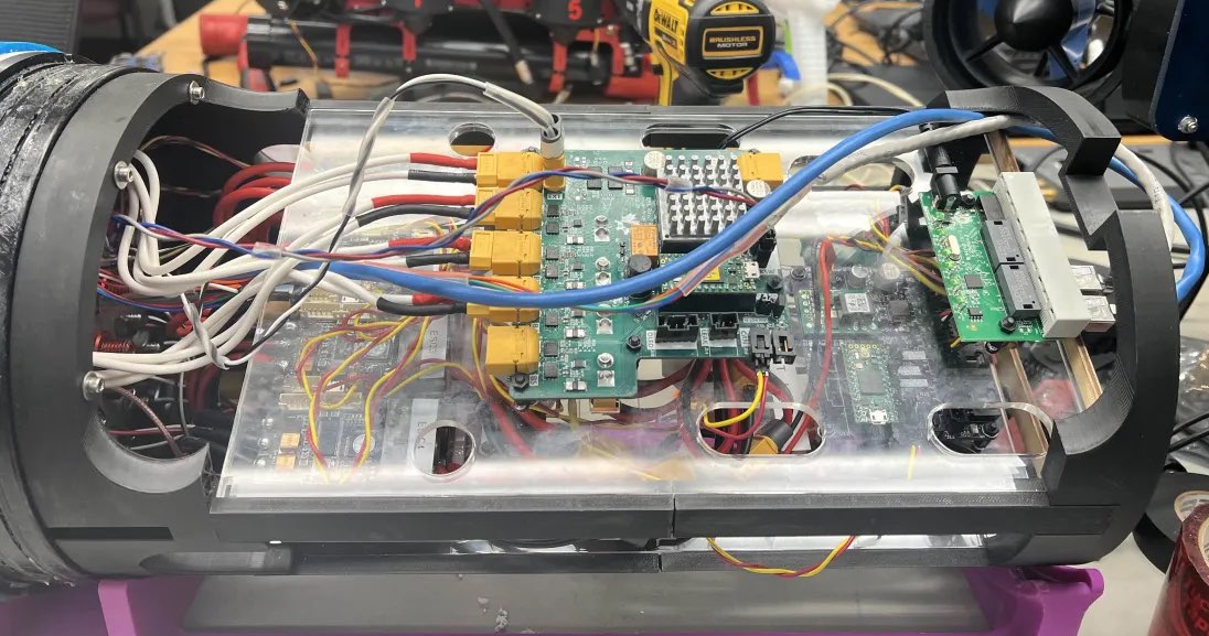
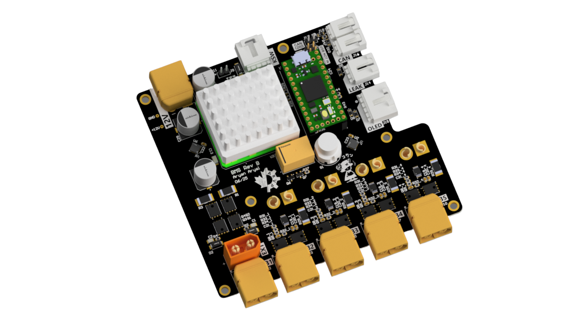
Kenai's power system is built around a new Battery Management System (BMS) and a centralized power distribution board. The BMS regulates incoming battery voltage and includes an integrated leak shutdown circuit, which, combined with the new robust kill switch, solidifies our system.
The power board converts the raw battery input into a stable 12V rail, eliminating the need for separate exposed voltage rails for each voltage level, which previously made wiring confusing and prone to errors. This system is new and was created in response to frequent failures and maintenance challenges with Arctos' power system. It was designed to be more resilient to voltage spikes, easier to assemble, and less prone to wiring and soldering errors.
By choosing robust components and simplifying the layout, the new design ensures the system can handle worst-case loads and physical stress more reliably. Testing involved validating voltage regulation under variable loads and verifying kill switch functionality during operation. The new BMS PCB has been utilized within Kenai since early 2026, with no recorded testing issues to date.
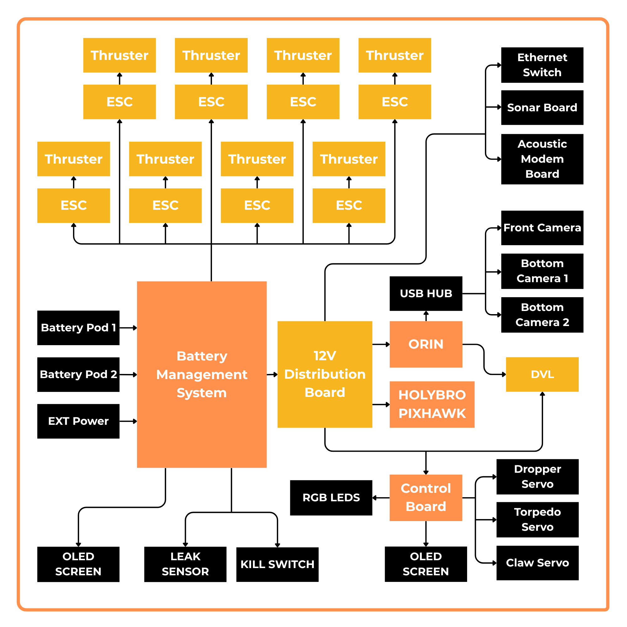
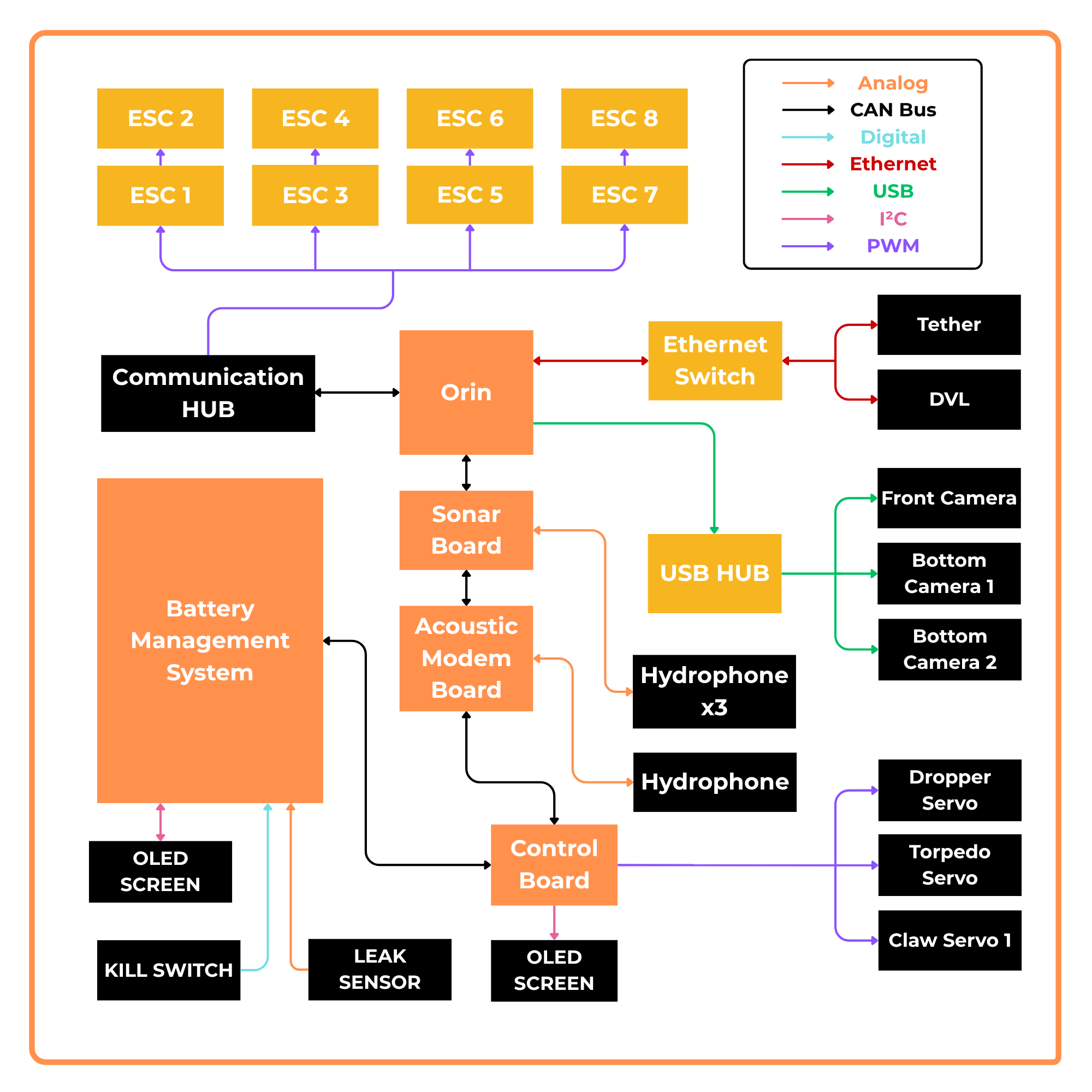
CAN bus is the main communication protocol linking all of the boards and auxiliary devices to the Jetson AGX Orin. Each board also has their own communication protocol to provide an interface to communicate with all our devices. Buffering was added to servo PWM signals and ESD protection was added to everything to eliminate more sources of error compared to previous designs.
Our communication systems are tested through a custom script for CAN bus so that when there is a problem, a logic analyzer for the CAN bus can be used to identify where exactly the fault is. In the future, we aim to improve the durability of our CAN bus by using a lower wire gauge and appropriately sized crimps and connectors to prevent loose crimps and weak connections.
This year, our focus was on improving precision and reliability while ensuring seamless integration with a new platform and updated hardware. Our software stack was improved with PID controller updates, revised configuration files for new subsystems and camera locations, and enhanced motion-planning stability for claw tasks.
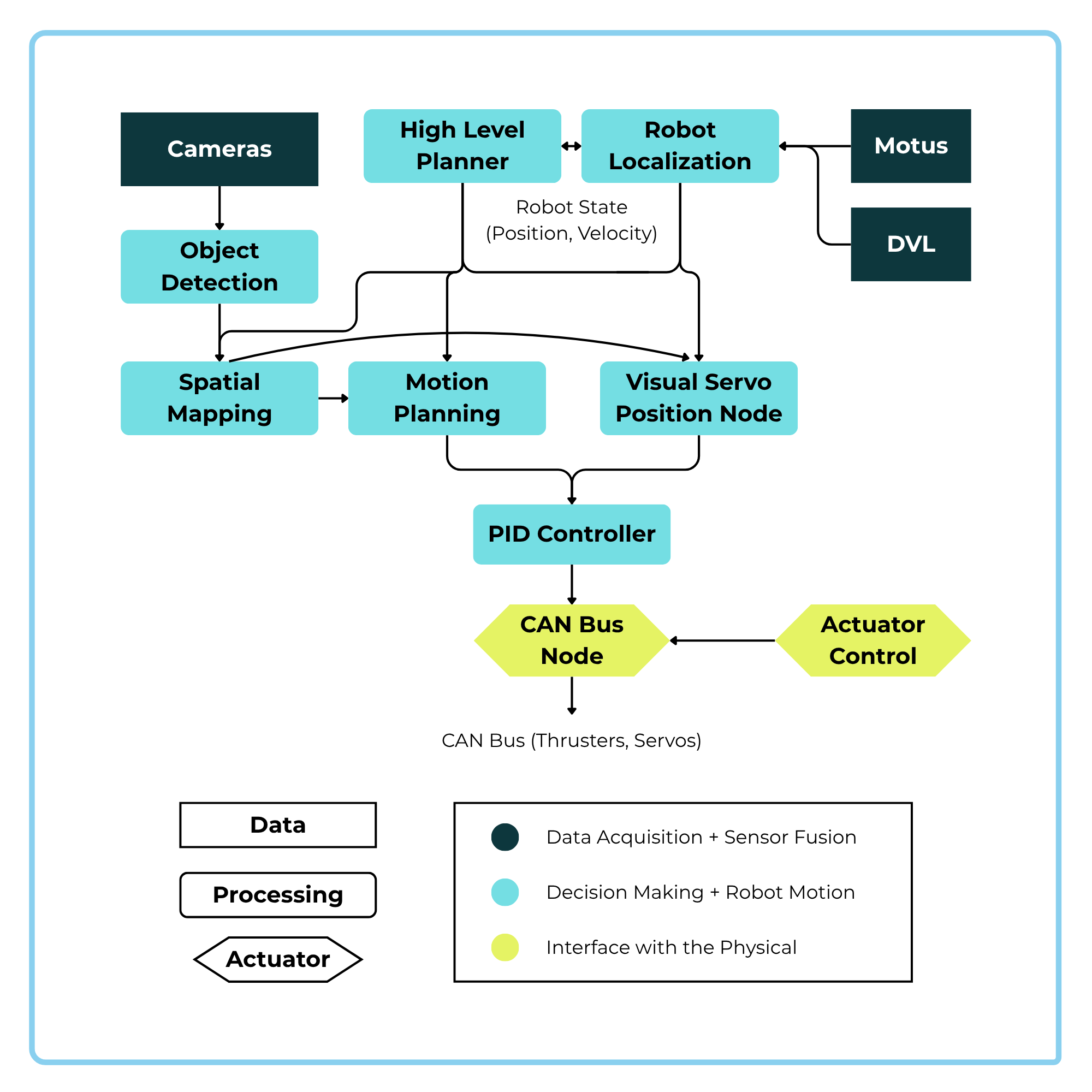
Our Nucleus DVL (doppler velocity logger), alongside a new IMU (the Motus from Advanced Navigation) and a magnetometer, determines the robot's velocity and overall state. This information is then sent to other nodes throughout the system. Mission planning is the highest level of decision-making in the robot — it uses behavior trees to plan out missions for the robot to execute. The motion planner node and visual servo node send target positions and velocities to our PID controller node. This node converts position / velocity targets into target thrusts, which are sent to the ESCs.
Alongside the main control pipeline is the camera and computer vision system. Our vision and mapping nodes use YOLO segmentation and oriented bounding boxes for more precise object detection and mapping.
Changes are first tested in our simulator and then validated in the pool on the robot. The simulator provides a fast feedback loop for software changes before they meet the water.
Most of the updates to our control and motion-planning systems focused on improving motion-planning performance and stability. One key addition was functionality that defines the degree of stability required at the end of a path before it is considered complete. Moving the stability code to the motion planner allows for more consistency in our software repository and allows us to be more flexible with the use of the motion planner.
The changes were tested in a simulator and are then validated in the pool on the robot. The torpedo task is a good benchmark for evaluating whether the robot can maintain sufficient positional and rotational stability during operation.
We also use visual servoing for the claw task to accurately orient the robot over items on the table and ensure stability while grabbing and placing them. Visual servoing is a robot control technique that uses real-time computer vision data (from cameras) within a feedback loop to guide the robot's motion.
Koda
Koda is a mini AUV, 19″ × 14″ × 9″ in size, built to be reliable and easy to deploy. Its hull is a Blue Robotics aluminum tube sealed with two double O-ring end caps. The electronic trays housed inside are 3D-printed and mounted to the rear end cap for easy removal or replacement. The frame is composed of a sheet-metal structure directly attached to both sides of the enclosure for robust mounting of thrusters, cameras, and sensors.
Despite its smaller size, Koda showcases many of the same mechanical design principles as Kenai — clean layouts, low-maintenance design, and high confidence in the water.
Koda carries a single external battery pod — compared to Kenai's two — housing two 14.4 V packs. Like Kenai, the pod is a small pressure vessel mounted on snap-fit brackets for quick removal without opening the main hull.
Inside the pod are two printed circuit boards that monitor battery voltage and internal pressure, displayed on a small screen for at-a-glance health checks. The system is activated externally using a magnet, so the pod stays sealed during normal operation.
To complete the it's Koda has a new hydroshell. This hydroshell does that the name implies and improves the hydrodynamics of Koda while it is moving in the water. It also servers a dual purpose and replaces the buoyancy pods to a much cleaner look.
Koda's electrical architecture was intentionally kept simple and modular, relying entirely on off-the-shelf components without a custom PCB. The system centers around the Pixhawk Jetson Baseboard Bundle from Holybro, combining real-time control and high-level autonomy in a compact, reliable form. By removing the need for a custom board, we reduced development time, minimized wiring complexity, and leaned into proven interfaces and protocols. Being quick, easy to integrate, and robust, the design reflects our broader goal with Koda.
Power for Koda is supplied by two 14.4V internal batteries, routed through a PM02D power module and UBEC included in the Pixhawk bundle. This setup provides clean, regulated power directly to both the Pixhawk and Jetson through the baseboard. ESCs are powered directly from the battery packs, and voltage regulation is handled locally within the system. This eliminates the need for a centralized power distribution board and keeps the power system simple, compact, and reliable, with fewer components and clearer wiring paths.
Koda's communication system is built around the integration between the Pixhawk and Jetson Nano via MAVLink, connected over serial through the baseboard. This allows high-level autonomy running on the Jetson to interface seamlessly with the real-time control handled by the Pixhawk. All communication lines are point-to-point, making the system more transparent, easier to debug, and less prone to silent failures.
The acoustic modem will be housed on mini bot which will only be capable of sending, not receiving signals.
This year, our focus was on improving the reliability of our software system and unifying our software stack into a single, dependable, and capable codebase. We also wanted to ensure seamless integration with our new hardware, including the transition to a Jetson Orin dev board, VESC ESCs for our thrusters, and a new SBG Ellipse Micro AHRS. To support this, we made several improvements to our software stack: localization updates, integration of the new AHRS, revised configuration files for new subsystems, and configuration for our new internal-environment electrical sensors. The AHRS determines the robot's velocity along with its roll, pitch, yaw, and acceleration, and this information is distributed to other nodes throughout the system. At the highest level of decision-making sits mission planning, which uses behavior trees to plan out the missions the robot executes. From there, the minibot motion planner node sends target velocities to our PID controller node, which issues thrust targets over CAN. These are then converted to UART commands for our new mini VESC ESCs that drive the thrusters. Running alongside the main control pipeline is the camera and computer vision system. Our vision and mapping nodes use YOLO segmentation and oriented bounding boxes for more precise object detection and mapping.